之前的文章简要介绍了开源INA226电流计模块的功能特点,本文将详细介绍INA226电流计模块的使用方法。
特性
- 感测总线电压范围:
0V - 36V - 高侧/低侧电流感测
- 电压、电流、功率测量
0.1%增益误差10uV偏移- 可配置测量平均值
- 16个可配置I2C地址
2.7V - 5.5V电源供电- 2路电源轨,可选为负载电源,作为 CH347高速USB桥接模块 扩展时,为
3.3V和5V - Alert指示灯
- 非共地连接时,可选远端电压感测
- 引脚兼容CH347模块,即插即用
硬件连接


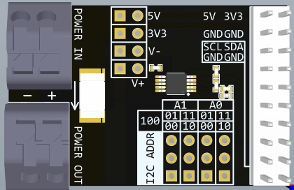
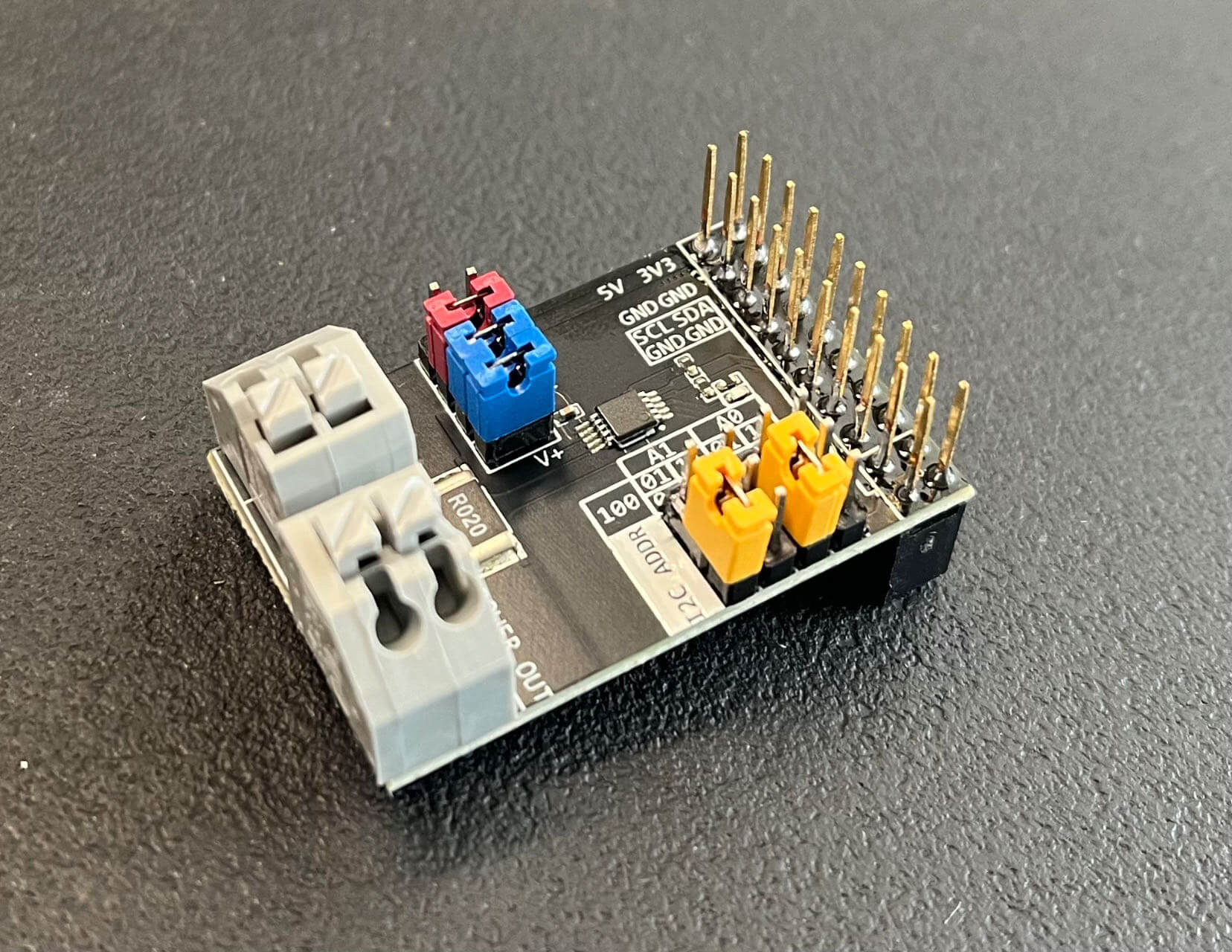
P4为10*2 2.54mm插针,是模块的电源和I2C接口,兼容CH347模块接口,可以直接插到CH347模块上使用。P4实际使用了加长排座,这样INA226模块插到CH347模块上时不会影响CH347模块连接其他设备,尤其是可以多个INA226模块同时插到CH347模块上使用,测量多路电流。
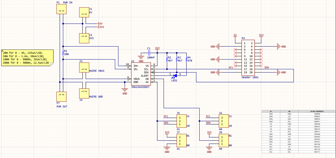
INA226模块上实际连接的插针只有8个引脚,1个5V电源,1个3.3V电源,1个SCL,1个SDA,4个GND。
INA226芯片实际使用3.3V电源,CH347模块上有5V和3.3V两路电源,所以在接口设计上这两路电源都接入INA226模块了,其中5V电源连接到J1,3.3V电源除了给INA226芯片供电,还连接到J2。J1和J2可以通过跳线帽选通为待测设备供电,也就是P1端口。
注意:
如果使用外部电源为待测设备供电,一定要将
J1和J2上的短路帽拔下来,否则会损坏模块!
J1和J2不能同时连接短路帽!
当仅测量电流时,可以像使用电流表一样,将待测点断开,然后将P1的1引脚和P2的2引脚,也就是电路板上标注的"+"的两个脚串入,这样就可以测量电流了。当电流流向与板子上箭头相同时为正,反向则为负。
当需要测量电压和功率时,接线就稍微复杂一些,既要测量电流,又要测量电压,此时需要将待测设备的电源接入P1,待测设备接入P2,注意极性,"+“接电源正极,”-"接电源负极。如果待测设备为5V或3.3V电源供电,电流小于500mA,则可以通过短路帽选通J1或J2来为待测设备供电,省去连接外部电源。如果待测设备电流较大,为了精确测量功率,则需要考虑远端测量电压,此时要将J3、J4上的短路帽拔下来,而使用杜邦线或其他导线将"V+"和"V-"连接到设备端的电源引脚,要注意极性不要接反,这样可以测量远端电压,从而排除电源线损耗对功率测量的影响。
J5 J6 J7 J8为电流计模块I2C地址设置,单个模块使用时保持短路帽默认位置即可,此时对应7位地址为0b1000000。多个模块同时使用时可以设置不同地址来区分各个模块。
LED为INA226芯片的Alert指示灯,可以通过软件设置报警逻辑和阈值来触发报警。
INA226模块目前发货默认感测电阻为20mΩ,对应电流测量范围为0 - 4A,分辨率为125uA,电压分辨率为1.25mV,非常给力,应对常规测量绰绰有余。并且可以编程自动化测量,连续监测记录数据。
示例程序
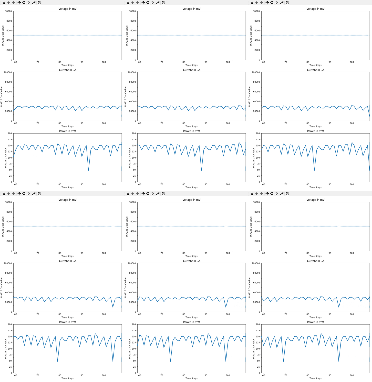
之前示例测试ESP32模块的电压、电流、功率:

代码如下:
import matplotlib.pyplot as plt
import matplotlib.animation as animation
import numpy as np
from time import sleep
from i2c_devices.ina226 import INA226# Initialize the INA226 sensor
sensor = INA226()def read_sensor_data():return [sensor.get_bus_voltage(), sensor.get_current(), sensor.get_power()]# Generator function to produce data from the sensor sensor
def generate_sensor_data():data_buffer = []while True:data = read_sensor_data()data_buffer.append(data)yield data_buffersleep(0.1)# Create a figure with 6 subplots for accelerometer and gyroscope data
fig, axs = plt.subplots(3, 1, figsize=(8, 12))# Initialize empty lines for the accelerometer and gyroscope data plots
lines = [axs[i].plot([], [], lw=2)[0] for i in range(3)]# Set the number of data points to be displayed on the plot
num_display_points = 50def init():for line in lines:line.set_data([], [])return linesdef update(frame):data_buffer = next(data_generator)# Generate the x-axis values (time steps) based on the number of data pointstime_steps = np.arange(len(data_buffer))# Get the starting index to display a specific number of data pointsstart_index = max(0, len(data_buffer) - num_display_points)# Update the plot data for accelerometer and gyroscopefor i in range(3):lines[i].set_data(time_steps[start_index:], [data[i] for data in data_buffer[start_index:]])axs[i].set_xlim(start_index, start_index + num_display_points - 1)# Update the x-axis limits for scrolling effectaxs[0].set_ylim(0, 10000)axs[1].set_ylim(0, 100000)axs[2].set_ylim(0, 200)return lines# Create the generator for sensor sensor data
data_generator = generate_sensor_data()# Create an animation for real-time plotting, update every 100 milliseconds (0.1 seconds)
ani = animation.FuncAnimation(fig, update, frames=range(100), init_func=init, blit=True, interval=100)# Add labels and title to each subplot
axis_labels = ['Voltage in mV', 'Current in uA', 'Power in mW']
for i in range(3):axs[i].set_title(f'{axis_labels[i]}')axs[i].set_xlabel('Time Steps')axs[i].set_ylabel('INA226 Data Value')plt.tight_layout()
plt.show()
sensor.close()
公众号 | FunIO
微信搜一搜 “funio”,发现更多精彩内容。
个人博客 | blog.boringhex.top


strlen函数模拟实现(三种方法))
![[AutoSar]BSW_Com010 CAN IF 模块介绍](http://pic.xiahunao.cn/[AutoSar]BSW_Com010 CAN IF 模块介绍)

)


编码打包的自定义格式的压缩包并未生成)


