
一.库函数版
1.硬件连接
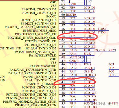


GPIO的输出方式:推挽输出
IO口输出为高电平时,P-MOS置高,输出为1,LED对应引脚处为高电平,而二极管正0极被电阻拉高,两端都为高电平,LED灭
IO输出为低电平同理

2.GPIO库函数说明
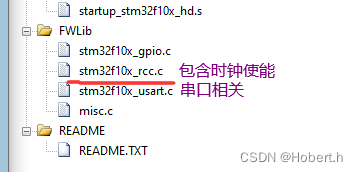
操作IO口必须引入源文件和头文件

(1)初始化函数
1.简要
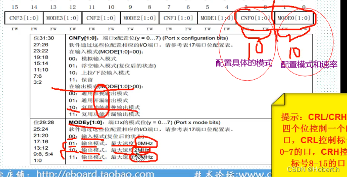
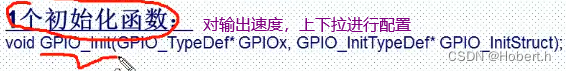 初始化模式
初始化模式


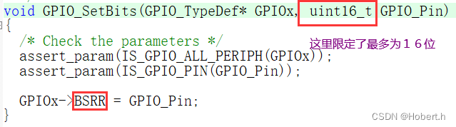
同时也控制BRR上下拉,最终控制ODR寄存器
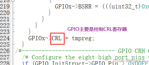
2.初始化函数(详细说明)
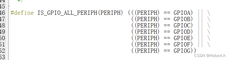
第一个参数作用:选择是哪一个IO口(GPIOA~GPIOG)
GPIO_TypeDef* GPIOx对应的结构体类型
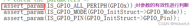
第二个参数作用:对参数进行初始化
GPIO_InitTypeDef* GPIO_InitStruct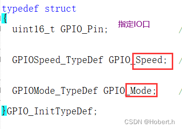 GPIO_Pin指定要配置的GPIO引脚。该参数可以是@ref GPIO_pins_define的任意值
typedef struct
{uint16_t GPIO_Pin;             /*!< Specifies the GPIO pins to be configured.This parameter can be any value of @ref GPIO_pins_define */GPIOSpeed_TypeDef GPIO_Speed;  /*!< Specifies the speed for the selected pins.This parameter can be a value of @ref GPIOSpeed_TypeDef */GPIOMode_TypeDef GPIO_Mode;    /*!< Specifies the operating mode for the selected pins.This parameter can be a value of @ref GPIOMode_TypeDef */
}GPIO_InitTypeDef;
3.示例

进行宏定义
#define GPIO_Pin_0                 ((uint16_t)0x0001)  /*!< Pin 0 selected */
#define GPIO_Pin_1                 ((uint16_t)0x0002)  /*!< Pin 1 selected */
#define GPIO_Pin_2                 ((uint16_t)0x0004)  /*!< Pin 2 selected */
#define GPIO_Pin_3                 ((uint16_t)0x0008)  /*!< Pin 3 selected */
#define GPIO_Pin_4                 ((uint16_t)0x0010)  /*!< Pin 4 selected */
#define GPIO_Pin_5                 ((uint16_t)0x0020)  /*!< Pin 5 selected */
#define GPIO_Pin_6                 ((uint16_t)0x0040)  /*!< Pin 6 selected */
#define GPIO_Pin_7                 ((uint16_t)0x0080)  /*!< Pin 7 selected */
#define GPIO_Pin_8                 ((uint16_t)0x0100)  /*!< Pin 8 selected */
#define GPIO_Pin_9                 ((uint16_t)0x0200)  /*!< Pin 9 selected */
#define GPIO_Pin_10                ((uint16_t)0x0400)  /*!< Pin 10 selected */
#define GPIO_Pin_11                ((uint16_t)0x0800)  /*!< Pin 11 selected */
#define GPIO_Pin_12                ((uint16_t)0x1000)  /*!< Pin 12 selected */
#define GPIO_Pin_13                ((uint16_t)0x2000)  /*!< Pin 13 selected */
#define GPIO_Pin_14                ((uint16_t)0x4000)  /*!< Pin 14 selected */
#define GPIO_Pin_15                ((uint16_t)0x8000)  /*!< Pin 15 selected */
#define GPIO_Pin_All               ((uint16_t)0xFFFF)  /*!< All pins selected */
定义了枚举类型
typedef enum
{ GPIO_Speed_10MHz = 1,GPIO_Speed_2MHz, GPIO_Speed_50MHz
}GPIOSpeed_TypeDef;
typedef enum
{ GPIO_Mode_AIN = 0x0,//模拟输入模式GPIO_Mode_IN_FLOATING = 0x04,//浮空输入模式(复位后的状态)GPIO_Mode_IPD = 0x28,//上拉/下拉输入模式GPIO_Mode_IPU = 0x48,//保留GPIO_Mode_Out_OD = 0x14,//通用开漏输出模式GPIO_Mode_Out_PP = 0x10,//通用推挽输出模式GPIO_Mode_AF_OD = 0x1C,//复用功能开漏输出模式GPIO_Mode_AF_PP = 0x18//复用功能推挽输出模式
}GPIOMode_TypeDef;
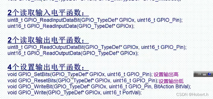
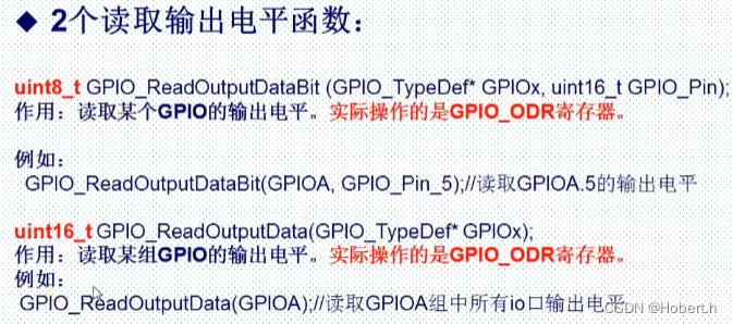
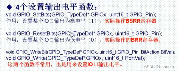
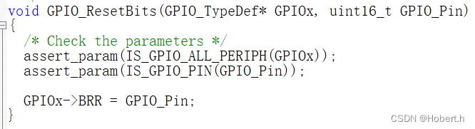
(2)其余函数

问题:查看函数定义时报错
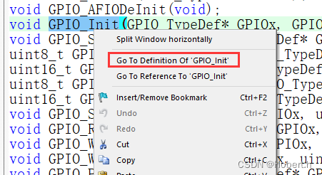
解决:

之后就可以成功转到定义了
------------------------------------------
3.代码实现
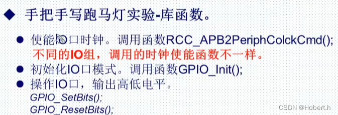
操作IO口之前,必须使能对应的时钟位
第一个参数
void RCC_APB2PeriphClockCmd(uint32_t RCC_APB2Periph, FunctionalState NewState)
{/* Check the parameters */assert_param(IS_RCC_APB2_PERIPH(RCC_APB2Periph));assert_param(IS_FUNCTIONAL_STATE(NewState));if (NewState != DISABLE){RCC->APB2ENR |= RCC_APB2Periph;}else{RCC->APB2ENR &= ~RCC_APB2Periph;}
}
第二个参数
#define IS_FUNCTIONAL_STATE(STATE) (((STATE) == DISABLE(不使能)) || ((STATE) == ENABLE(使能)))
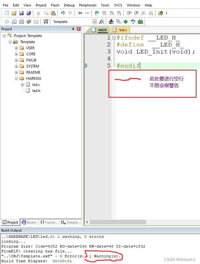
(1)创建HAREWARE文件,led.c,led.h
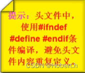
注:为避免重复调用头文件,通过预编译的方式,判断是否已经定义了一个唯一的标识符(所以这个标识符的命名是不重要的)
头文件要对MDK添加路径
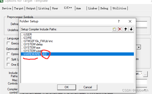
注:
(2)led文件编写
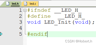
h
#ifndef __LED_H_
#define  __LED_H_
void LED_Init(void);#endif
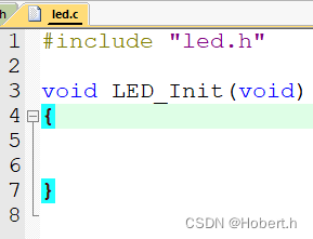
c
//#include "led.h"
#include "stm32f10x.h"
void LED_Init(void)
{GPIO_InitTypeDef GPIO_InitStructure;RCC_APB2PeriphClockCmd(RCC_APB2Periph_GPIOA,ENABLE);//使能GPIOB时钟RCC_APB2PeriphClockCmd(RCC_APB2Periph_GPIOD,ENABLE);//使能GPIOB时钟GPIO_InitStructure.GPIO_Mode=GPIO_Mode_Out_PP;/*初始化PA_8*/GPIO_InitStructure.GPIO_Pin=GPIO_Pin_8;GPIO_InitStructure.GPIO_Speed=GPIO_Speed_50MHz;GPIO_Init(GPIOA,&GPIO_InitStructure);GPIO_SetBits(GPIOA,GPIO_Pin_8);//PA_8输出高电平GPIO_InitStructure.GPIO_Mode=GPIO_Mode_Out_PP;/*初始化PD_2*/GPIO_InitStructure.GPIO_Pin=GPIO_Pin_2;GPIO_InitStructure.GPIO_Speed=GPIO_Speed_50MHz;GPIO_Init(GPIOD,&GPIO_InitStructure);GPIO_SetBits(GPIOD,GPIO_Pin_2);//PD_2输出高电平
}
(3)main文件编写
#include "stm32f10x.h"
#include "led.h"
#include "delay.h"
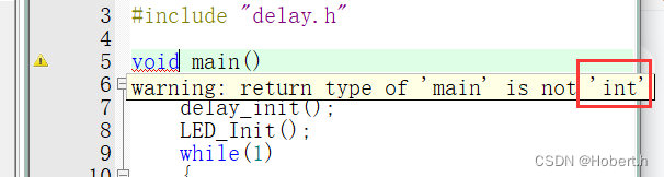
int main()
{delay_init();LED_Init();while(1){GPIO_SetBits(GPIOA,GPIO_Pin_8);GPIO_SetBits(GPIOD,GPIO_Pin_2);delay_ms(300);GPIO_ResetBits(GPIOA,GPIO_Pin_8);GPIO_ResetBits(GPIOD,GPIO_Pin_2);delay_ms(300);}}二.寄存器版
1.硬件连接
看库函数版,过程一样
2.代码实现
过程
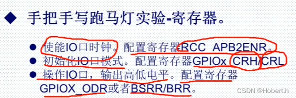
GPIO都是挂载在APB2总线下
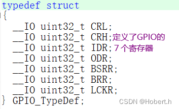
#define RCC ((RCC_TypeDef *) RCC_BASE)typedef struct
{__IO uint32_t CR;__IO uint32_t CFGR;__IO uint32_t CIR;__IO uint32_t APB2RSTR;__IO uint32_t APB1RSTR;__IO uint32_t AHBENR;__IO uint32_t APB2ENR;__IO uint32_t APB1ENR;__IO uint32_t BDCR;__IO uint32_t CSR;#ifdef STM32F10X_CL __IO uint32_t AHBRSTR;__IO uint32_t CFGR2;
#endif /* STM32F10X_CL */ #if defined (STM32F10X_LD_VL) || defined (STM32F10X_MD_VL) || defined (STM32F10X_HD_VL) uint32_t RESERVED0;__IO uint32_t CFGR2;
#endif /* STM32F10X_LD_VL || STM32F10X_MD_VL || STM32F10X_HD_VL */
} RCC_TypeDef;注: 要写成int main()
(1)led.c编写
#include "stm32f10x.h"
void LED_Init(void)
{RCC->APB2ENR|=(1<<2);//使能A/*使能时钟*/RCC->APB2ENR|=(1<<5);//使能DGPIOA->CRH|=0x00000003;/*设置推挽输出模式*/GPIOD->CRL|=0x00000300;
}
(2)main文件的编写
配置ODR寄存器
#include "stm32f10x.h"
#include "led.h"
#include "delay.h"int main()
{delay_init();LED_Init();delay_ms(100);while(1){GPIOA->ODR=1<<8;GPIOD->ODR=1<<2;delay_ms(500);GPIOA->ODR=~(1<<8);GPIOD->ODR=~(1<<2);delay_ms(500);}}
配置BRR与BSRR寄存器、
#include "stm32f10x.h"
#include "led.h"
#include "delay.h"int main()
{delay_init();LED_Init();delay_ms(100);while(1){GPIOA->BSRR=1<<8;GPIOD->BSRR=1<<2;delay_ms(500);GPIOA->BRR=(1<<8);GPIOD->BRR=(1<<2);delay_ms(500);}}
三.位操作
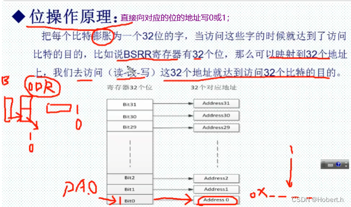
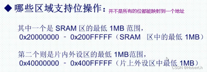
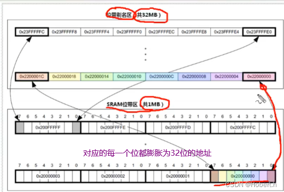
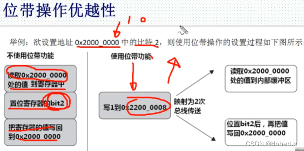
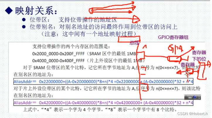
1.位操作基本原理
2.硬件连接
看库函数版,过程一样
3.代码实现
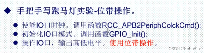
(1)led.c文件编写
下面的是库函数版,也可以写成寄存器版
//#include "led.h"
#include "stm32f10x.h"
void LED_Init(void)
{GPIO_InitTypeDef GPIO_InitStructure;RCC_APB2PeriphClockCmd(RCC_APB2Periph_GPIOA,ENABLE);//使能GPIOB时钟RCC_APB2PeriphClockCmd(RCC_APB2Periph_GPIOD,ENABLE);//使能GPIOB时钟GPIO_InitStructure.GPIO_Mode=GPIO_Mode_Out_PP;/*初始化PA_8*/GPIO_InitStructure.GPIO_Pin=GPIO_Pin_8;GPIO_InitStructure.GPIO_Speed=GPIO_Speed_50MHz;GPIO_Init(GPIOA,&GPIO_InitStructure);GPIO_SetBits(GPIOA,GPIO_Pin_8);//PA_8输出高电平GPIO_InitStructure.GPIO_Mode=GPIO_Mode_Out_PP;/*初始化PD_2*/GPIO_InitStructure.GPIO_Pin=GPIO_Pin_2;GPIO_InitStructure.GPIO_Speed=GPIO_Speed_50MHz;GPIO_Init(GPIOD,&GPIO_InitStructure);GPIO_SetBits(GPIOD,GPIO_Pin_2);//PD_2输出高电平
}
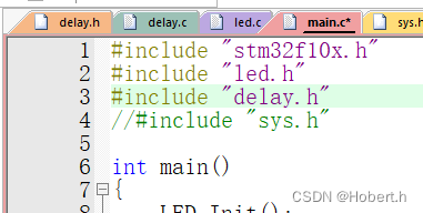
(2)main文件编写
#include "stm32f10x.h"
#include "led.h"
#include "delay.h"
#include "sys.h"int main()
{LED_Init();delay_init();while(1){PAout(8)=1;PDout(2)=1;delay_ms(500);PAout(8)=0;PDout(2)=0;		delay_ms(500);}
}
注:
由于在delay.h文件中已经引用了sys.h所以可以不用在main文件声明sys.h


)


java#Springboot#mysql旅游景点订票系统68524-计算机毕业设计项目选题推荐)


