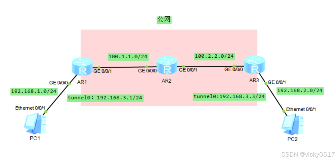
一、实验拓扑
二、实验要求
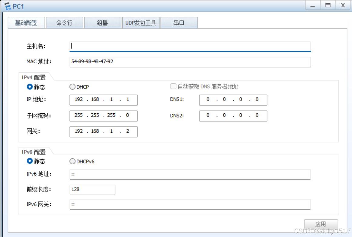
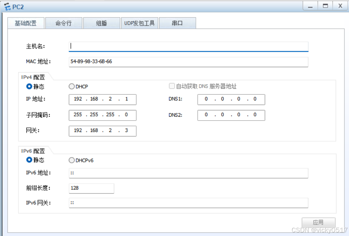
1、按照图示配置IP地址
2、在R1和R3上配置默认路由使公网区域互通
3、在R1和R3上配置GRE VPN,使两端私网能够互相访问,Tunnel口IP地址如图
4、在R1和R3上配置RIPv2或者ospf或者静态,来传递两端私网路由
三、实验步骤
1、配置IP地址部分
[R1]int g0/0/0
[R1-GigabitEthernet0/0/0]ip add 192.168.1.2 24
[R1-GigabitEthernet0/0/0]int g0/0/1
[R1-GigabitEthernet0/0/1]ip add 100.1.1.1 24
[R2]int g0/0/0
[R2-GigabitEthernet0/0/0]ip add 100.1.1.2 24
[R2-GigabitEthernet0/0/0]int g0/0/1
[R2-GigabitEthernet0/0/1]ip add 100.2.2.2 24
[R3]int g0/0/0
[R3-GigabitEthernet0/0/0]ip add 100.2.2.3 24
[R3-GigabitEthernet0/0/0]int g0/0/1
[R3-GigabitEthernet0/0/1]ip add 192.168.2.3 24
2、在R1和R3上配置默认路由使公网区域互通
[R1]ip route-static 100.2.2.0 24 100.1.1.2
[R3]ip route-static 100.1.1.0 24 100.2.2.2
3、在R1和R3上配置GRE VPN,使两端私网能够互相访问,Tunnel口IP地址如图
分析:根据需求,需要在R1和R3上创建GRE Tunnel口,配置源地址和目的地址为本端公网地址和对端公网地址。
Step 1:在R1上创建Tunnel口,设置隧道协议为GRE,源地址:本端公网地址,目的地址:对端公网地址
[R1]interface Tunnel 0/0/0
[R1-Tunnel0/0/0]tunnel-protocol gre
R1-Tunnel0/0/0]ip add 192.168.3.1 24
[R1-Tunnel0/0/0]source 100.1.1.1
[R1-Tunnel0/0/0]destination 100.2.2.3
[R1]dis ip int b
Interface IP Address/Mask Physical Protocol
GigabitEthernet0/0/0 192.168.1.2/24 up up
GigabitEthernet0/0/1 100.1.1.1/24 up up
GigabitEthernet0/0/2 unassigned down down
NULL0 unassigned up up(s)
Tunnel0/0/0 192.168.3.1/24 up up Step2:在R3上创建Tunnel口,模式为GRE,源地址:本端公网地址,目的地址为:对端公网地址。
[R3]int Tunnel 0/0/0
[R3-Tunnel0/0/0]ip address 192.168.3.3 24
[R3-Tunnel0/0/0]tunnel-protocol gre
[R3-Tunnel0/0/0]source 100.2.2.3
[R3-Tunnel0/0/0]destination 100.1.1.1
[R3]dis ip int br
Interface IP Address/Mask Physical Protocol
GigabitEthernet0/0/0 100.2.2.3/24 up up
GigabitEthernet0/0/1 192.168.2.3/24 up up
GigabitEthernet0/0/2 unassigned down down
NULL0 unassigned up up(s)
Tunnel0/0/0 192.168.3.3/24 up up
4、在R1和R3上配置RIPv2或者ospf或者静态,来传递两端私网路由
分析:R1和R3通过RIP来传递私网路路由,由于私网报文要通过VPN隧道口传输,所以需要把Tunnel口宣告进RIP,使R1和R3通过Tunnel口传递路由.
Step1:在R1上配置RIP,宣告业务网段和Tunnel口网段
[R1]rip 1
[R1-rip-1]version 2
[R1-rip-1]undo summary
[R1-rip-1]network 192.168.1.0
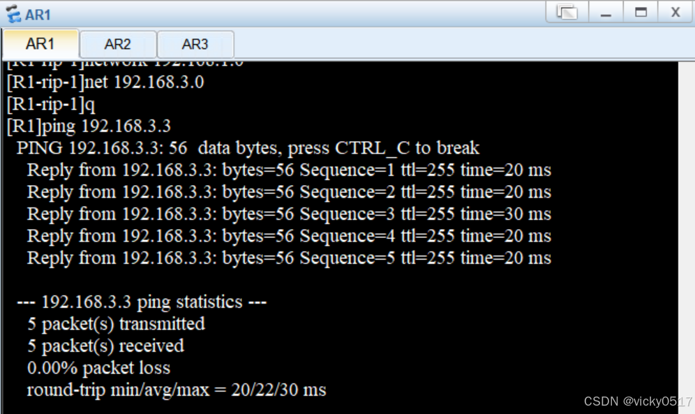
[R1-rip-1]net 192.168.3.0
[R1-rip-1]quit
Step2:在R3上配置RIP,宣告业务网段和Tunnel口网段
[R3]rip 1
[R3-rip-1]version 2
[R3-rip-1]undo summary
[R3-rip-1]net 192.168.3.0
[R3-rip-1]net 192.168.2.0
[R3-rip-1]quit
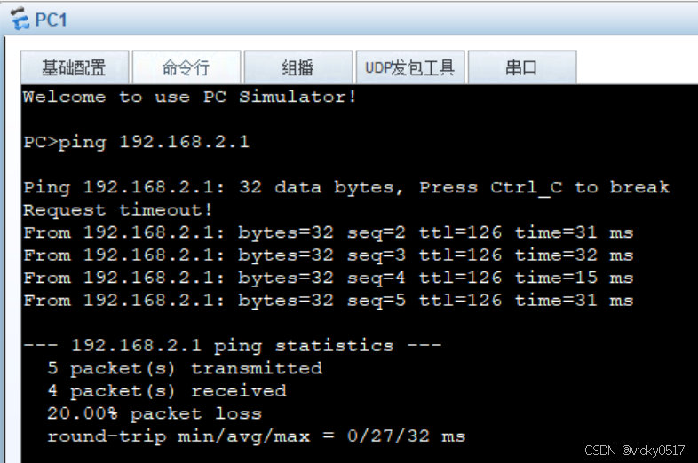
效果测试:在PC1上Ping PC2,可以Ping通
在R1上pingR3的隧道口,可以ping通
实验中需要注意的是:在配置RIPv2的过程中,需删除对汇总进行删除,以防止路由环路。


)
)
)


