介绍
其实我们知道,用FPGA实现乘法器并不是一件很简单的事,而且在FPGA中也有乘法器的IP核可以直接调用,我这里完全就是为了熟悉一些FPGA的语法然后写了这样一个电路。
串-并型乘法器模块
从字面上看,串-并乘法器就是其中一个乘数是串行的,另一位乘数是并行的。我在这里只描述一下模块的输入输出端口,相比于并行乘法器,串-并型乘法器占用的资源更少。
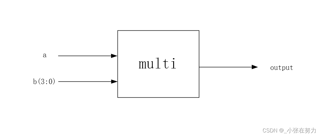
在这里,a是串行的数据,b是并行的4位数据,output也是串行的数据。
设计文件
这里我把基础的与门,D触发器和乘法器都给省略掉了。
--pipe元件
library ieee;
use ieee.std_logic_1164.all;
use work.my_component.all;
entity pipe is
port( a,b,clk,rst : in std_logic;
d_reg_out : out std_logic);
end entity;
architecture behavior of pipe is
signal f_add_outc,cin,f_add_outs : std_logic;
begin
u1 : component f_add
port map(a,b,cin,f_add_outs,f_add_outc);
u2 : component d_reg
port map(f_add_outc,clk,rst,cin);
u3 : component d_reg
port map(f_add_outs,clk,rst,d_reg_out);
end architecture;
--packeg声明元件
library ieee;
use ieee.std_logic_1164.all;
package my_component is
------------------------------------
component and_2 is
port( a,b : in std_logic;
and_2_out: out std_logic);
end component;
------------------------------------
component d_reg is
port( d_reg_in,clk,rst : in std_logic;
d_reg_out : out std_logic);
end component;
------------------------------------
component f_add is
port (a,b,cin : in std_logic;
f_add_outs,f_add_outc : out std_logic);
end component;
------------------------------------
component pipe is
port( a,b,clk,rst : in std_logic;
d_reg_out : out std_logic);
end component;
end package;
顶层文件
library ieee;
use ieee.std_logic_1164.all;
use work.my_component.all;
entity multiplier is
port( a,rst,clk : in std_logic;
b : in std_logic_vector(3 downto 0);
output : out std_logic);
end entity;
architecture behavior of multiplier is
signal and_out,reg_out : std_logic_vector(3 downto 0);
begin
u1: component and_2 port map(a,b(3),and_out(3));
u2: component and_2 port map(a,b(2),and_out(2));
u3: component and_2 port map(a,b(1),and_out(1));
u4: component and_2 port map(a,b(0),and_out(0));
u5: component d_reg port map(and_out(3),clk,rst,reg_out(3));
u6: component pipe port map(and_out(2),reg_out(3),clk,rst,reg_out(2));
u7: component pipe port map(and_out(1),reg_out(2),clk,rst,reg_out(1));
u8: component pipe port map(and_out(0),reg_out(1),clk,rst,reg_out(0));
output <= reg_out(0);
end behavior;
测试文件
在测试文件中,我只对顶层文件进行了测试,有兴趣的小伙伴可以对各个信号进行仿真验证。
library ieee;
use ieee.std_logic_1164.all;
use work.my_component.all;
entity tb_multiplier is
end entity;
architecture behavior of tb_multiplier is
component multiplier is
port( a,rst,clk : in std_logic;
b : in std_logic_vector(3 downto 0);
output : out std_logic);
end component;
signal a,rst,clk : std_logic := '0';
signal output : std_logic := '1';
signal b : std_logic_vector(3 downto 0);
begin
dut : multiplier
port map(a,rst,clk,b,output);
process
begin
clk <= '1';
wait for 10ns;
clk <= '0';
wait for 10ns;
end process;
process
begin
a <= '0';
b <= "1101";
wait for 40ns;
a <= '1';
wait for 40ns;
a <= '0';
wait for 80ns;
end process;
end architecture;
仿真结果
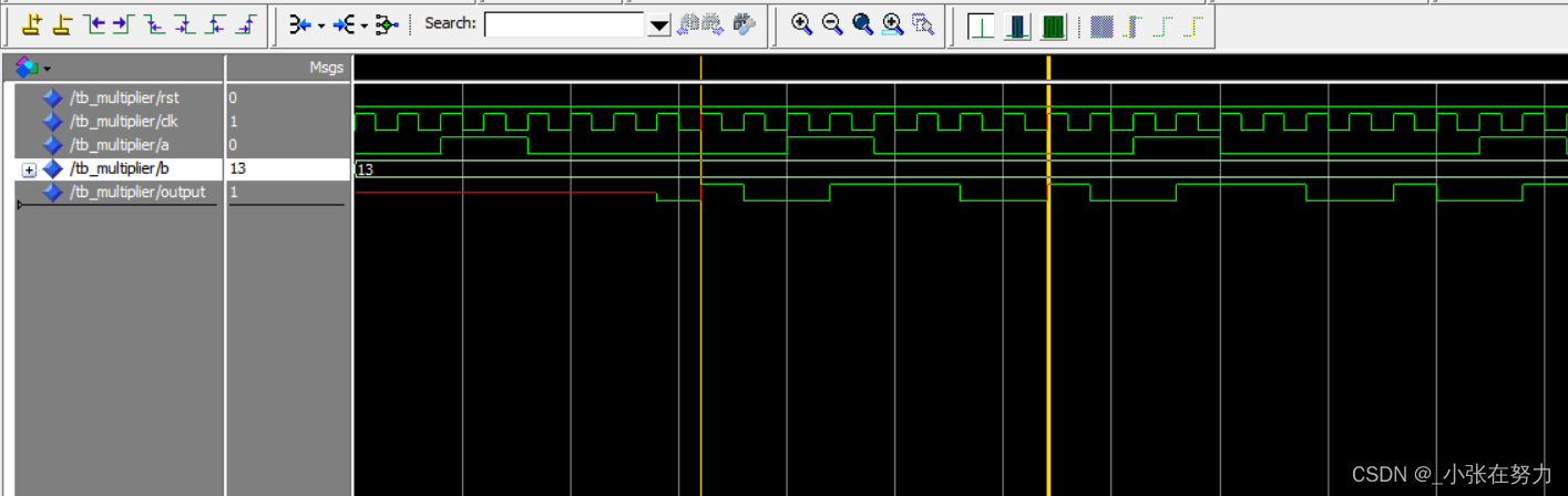
在仿真测试中,我们把a看作是4位串行的数据,我们看黄线中间的8位数据,a是0011,后面紧跟4个0,b是1101,输出结果是10011100,对应十进制数相乘,结果是正确的。
结语
确实是不太好写的,对于这种比较复杂的电路,一定要去建立一个一个的元件,然后将各个元件进行连接,这样会容易很多。
更完整的代码在相关的压缩包,有问题大家留言。


 使用详解)
)
—— 事务)
是负责查找和加载模板文件的组件)


)

v16.84正式激活版)


